3D-Printed Quasi-Direct Drive Actuator and Custom 3-Phase Inverter
Driving brushless motors using a custom PCB
Project at a glance
- Designed a four-layer STM32 inverter for three-phase BLDC motor control.
- Integrated encoder feedback, current sensing, CAN, and regenerative overvoltage protection.
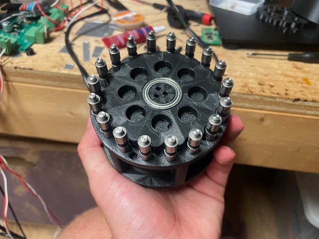
- Built a modular 19:1 3D-printed cycloidal gearbox with measured torque up to 20Nm
I designed a custom ESC/inverter to better understand three-phase motors and their control. I also designed a modular cycloidal gearbox and housing so the actuator can be reused in future projects (stay tuned). I am on iteration #5 of the PCB and iteration #3 on the gearbox/actuator as of now.
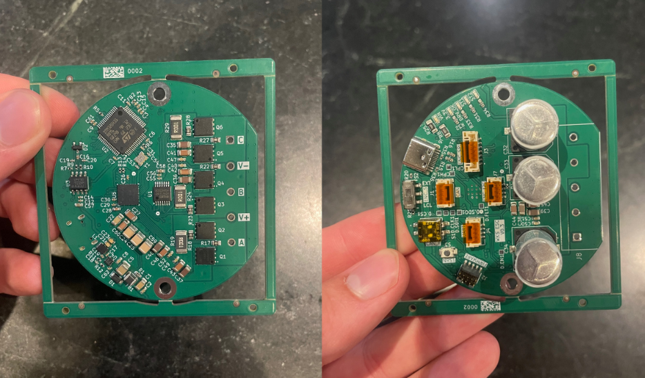
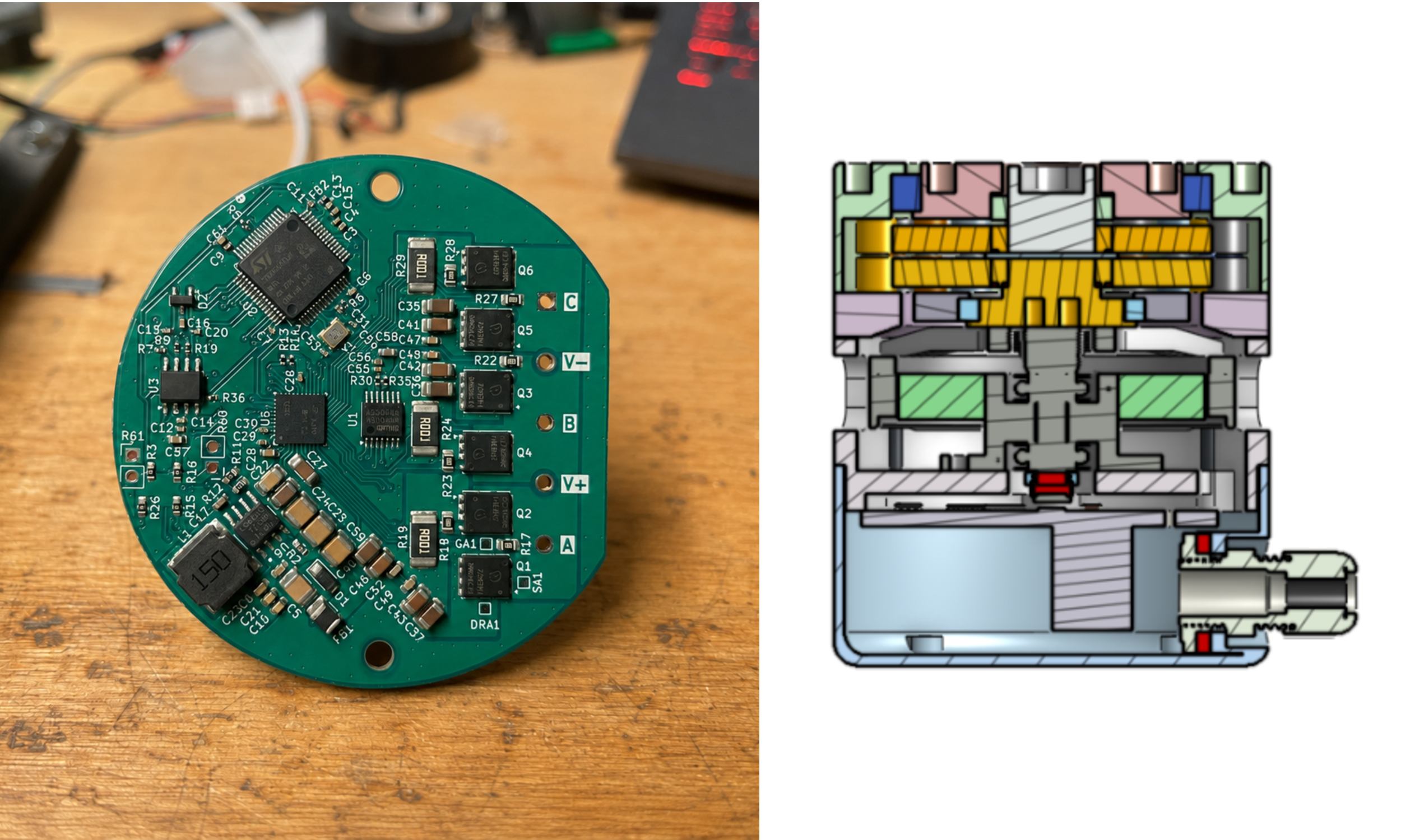
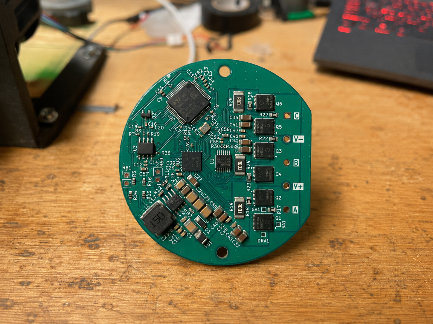
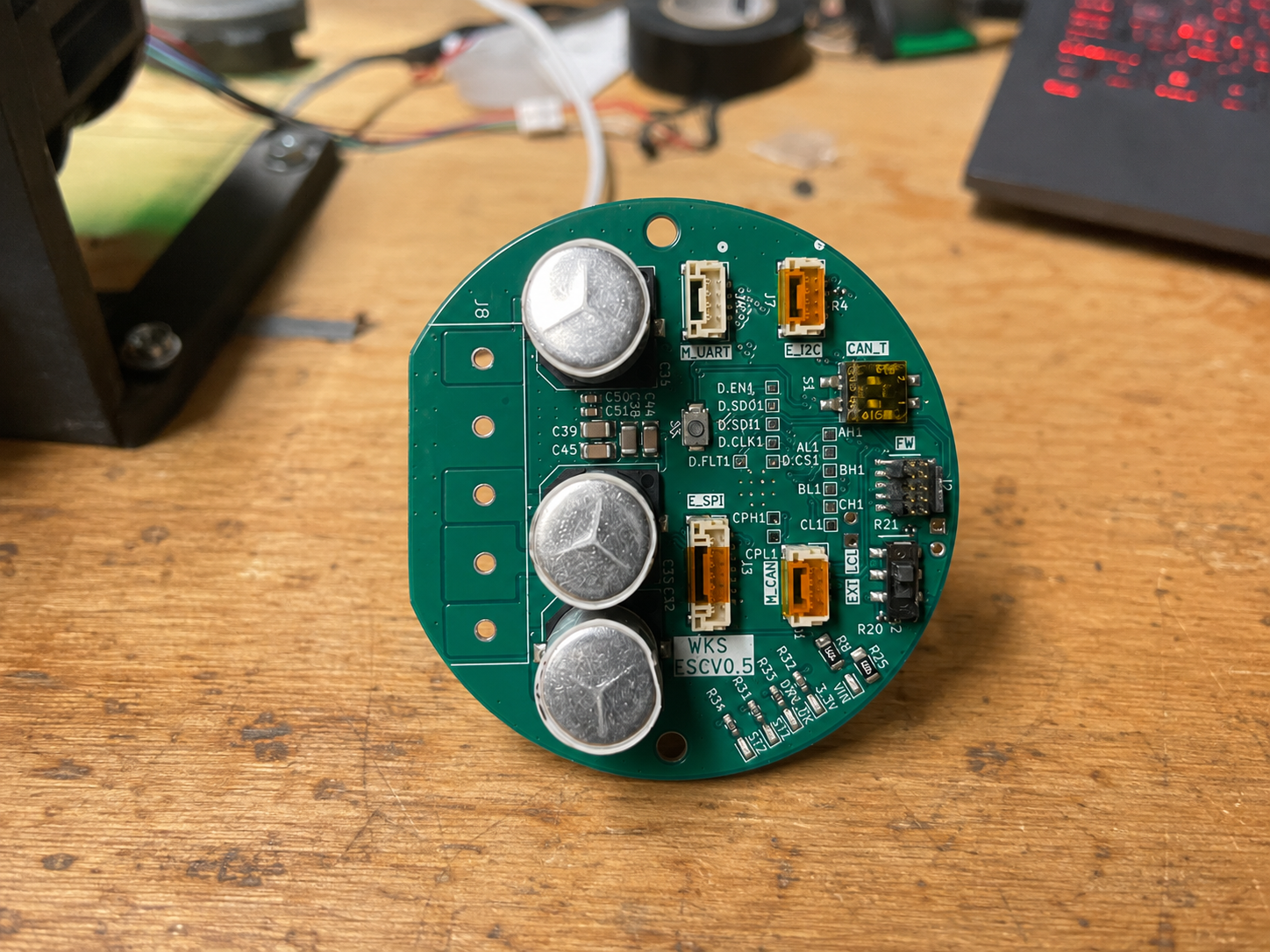
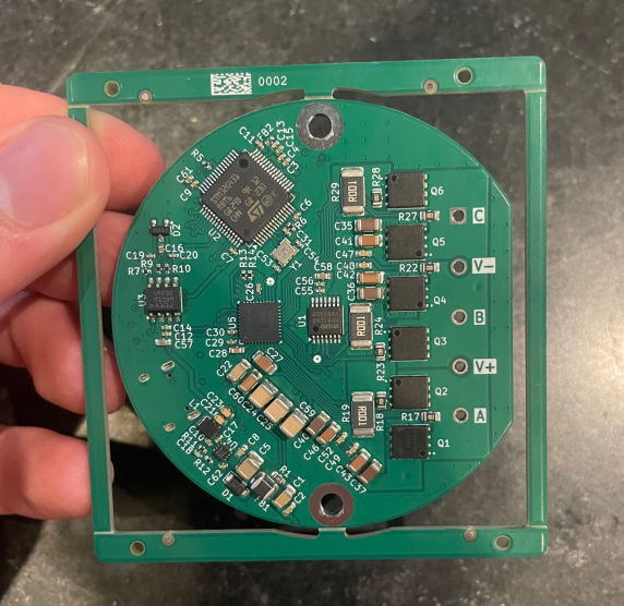
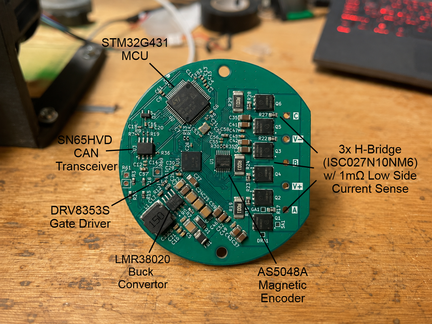 ESC V0.5 - 4 layer board
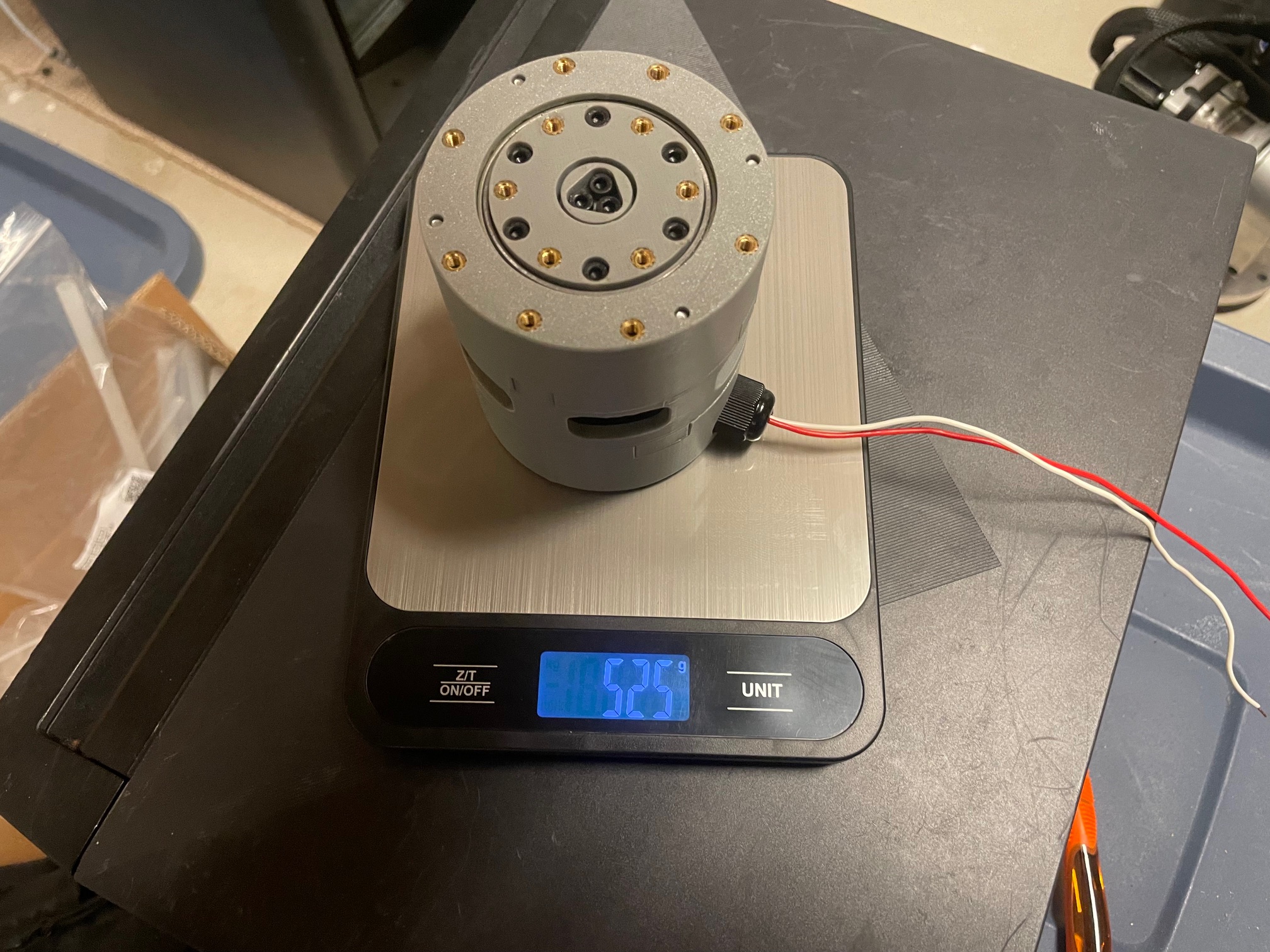 Actuator v3 - 19:1 cycloid, PLA+ housing
What/How?
Electrical Design
I designed the board in KiCad. It is a 4-layer board. It uses an STM32G4341 microcontroller to command a DRV8353S gate driver to control the three half-bridges. I used ISC027N10NM6 NMOS Transistors because of their low 2.7mOhm Rds (on), low gate charge capacitance (58nC Qg and 62nC Qrr), and 192A max Id. An onboard AS5048A encoder collects 14-bit rotor angle readings from the motor at 11.25 kHz, which is suitable for FOC which works smoother with larger encoder refresh rates. For external communication, I included an SN65HVD230DR CAN transceiver. The board also supports external UART communication as well.
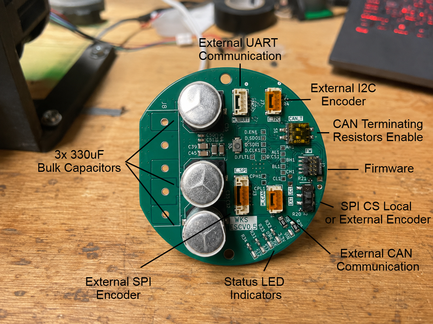
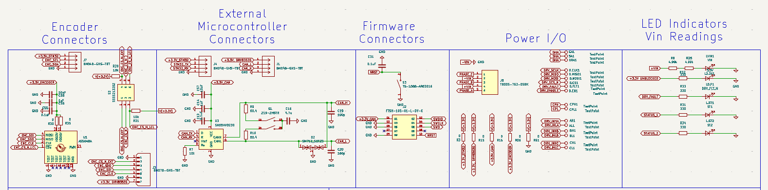 AS5048A Encoder Circuit, SN65HVD CAN circuit (with optional terminating resistors), Power I/O, LED indicators
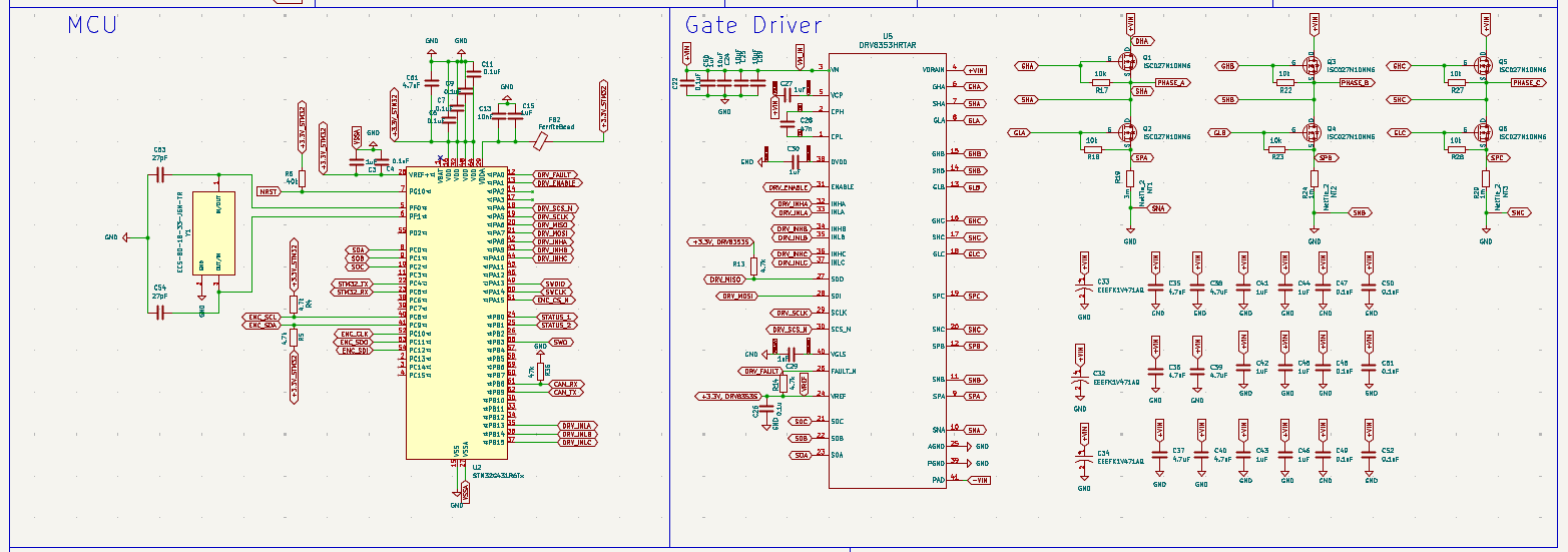 MCU Connection and Gate Driver Circuit
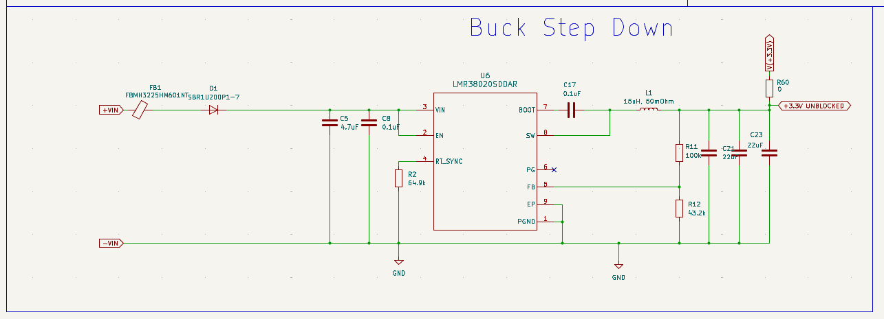 60V max input to 3.3V output using LMR3802
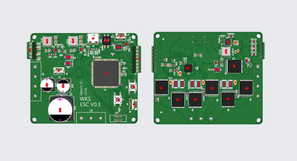
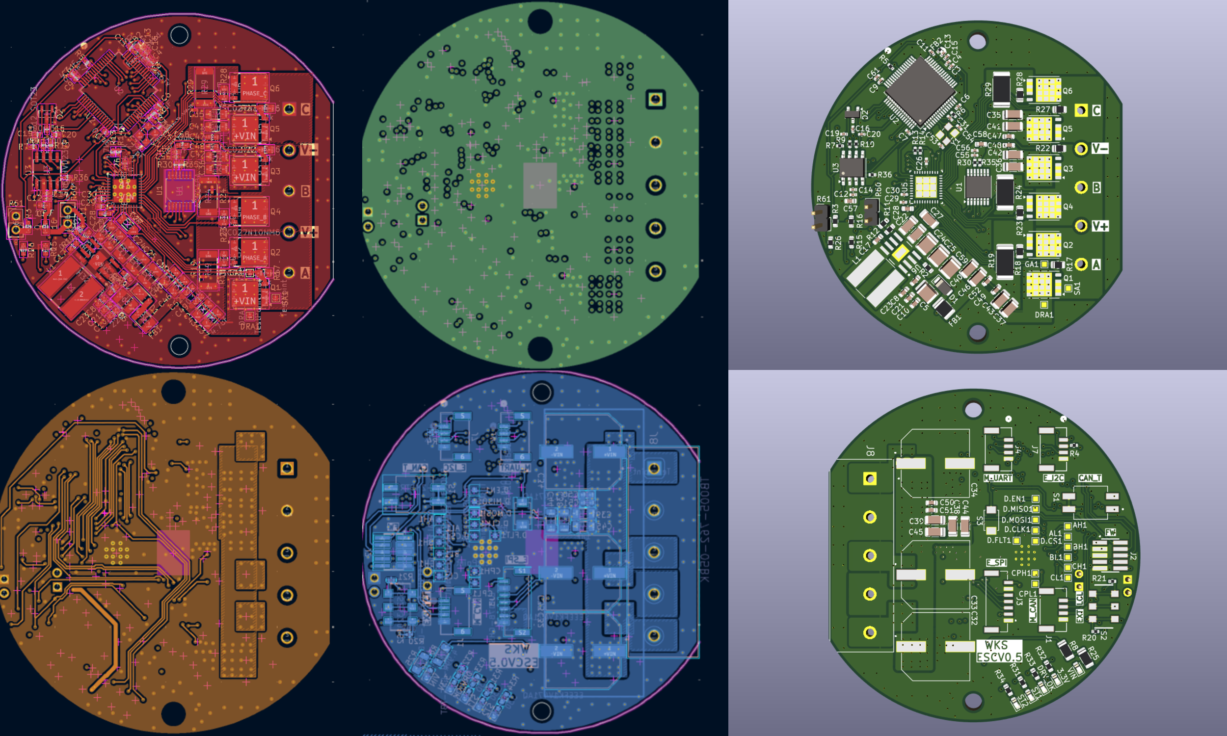 Four layer architecture
I am on my fifth version to date. I wanted to share what I have learned from the failed iterations so far:
Version 3/4 - Buck Convertor Problems
In my third version I used the LMR36506R53 buck to step down 60V (max) to 3.3V to power all of the ICs. This buck overheated because I made a design misjudgement: MODE/SYNC tied to VCC → forced FPWM → continuous 2.2 MHz switching → circulating current + switching losses → tiny 2×2 mm regulator gets much hotter than expected.
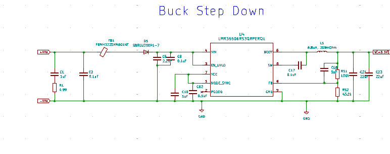 MODE_SYNC tied to VCC asserts FPWM mode (see page 27 here)
This meant it didnt operate as efficiently and lead to overheating:
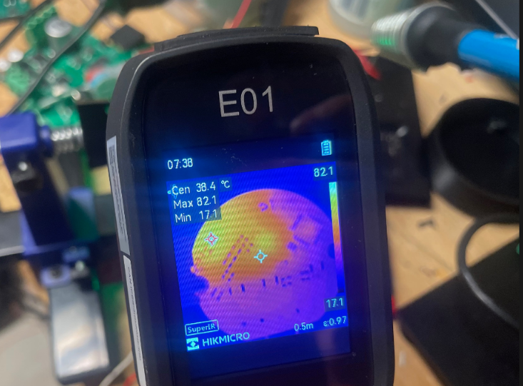 85 degrees Celsius with 24Vin!
This version was usable for low modulation demos but I would get undervoltage lockout faults when using a more extreme duty cycle on the h-bridges. I replaced the LM36506R53 with a more heavy-duty 2A LMR38020 buck in V4 and this solved my 3.3V power issues.
Version 2 - Layout Problems
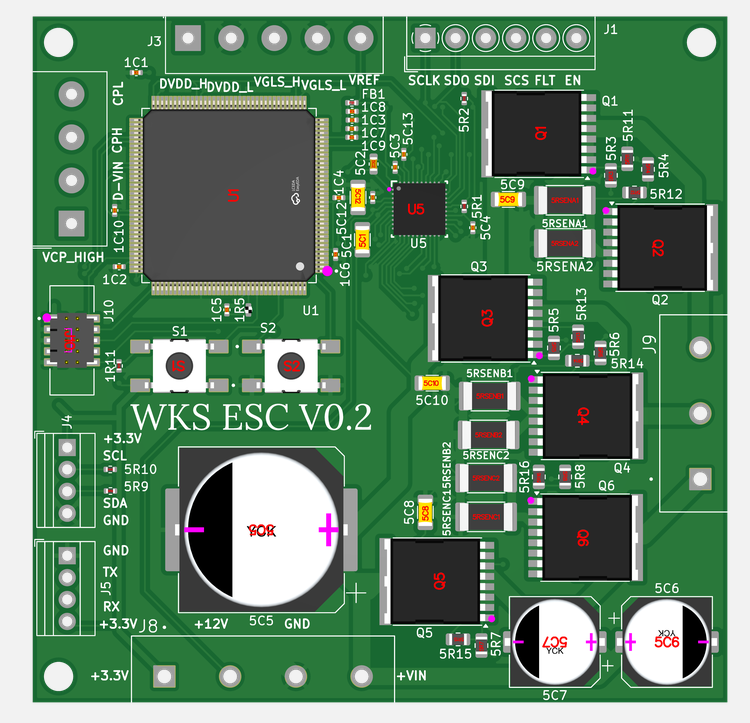
My second version fixed the missing components from version 1 but did not optimize the layout of the high frequency capacitors, which led to incredibly unsmooth commutation. Having high frequency (0.1uF, 1uF) capcitors near the high side MOSFET is critical to minimize the loop area (V+ -> through H-bridge -> V-). Reducing the loop area reduces unwanted electromagnetic interference which can cause the unstable motion as you can see below.
The layout reccomendations from TI for the DRV8353S circuit has ceramic capacitors placed incredibly close to the high side mosfet (light red planes).
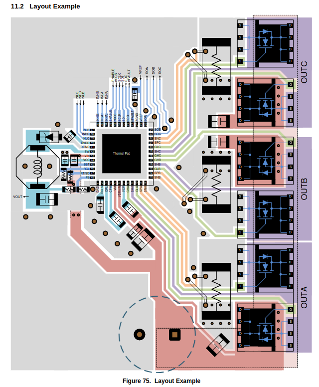
Comparing to my circuit above, the MOSFETS are staggered and the bypass capacitors are therefore very far from the low side MOSFET – this leads to a large induced loop and a lot of EMI. I was careful to copy this layout as best as possible in V3 onwards and it paid off.
Version 1 - Missing Components
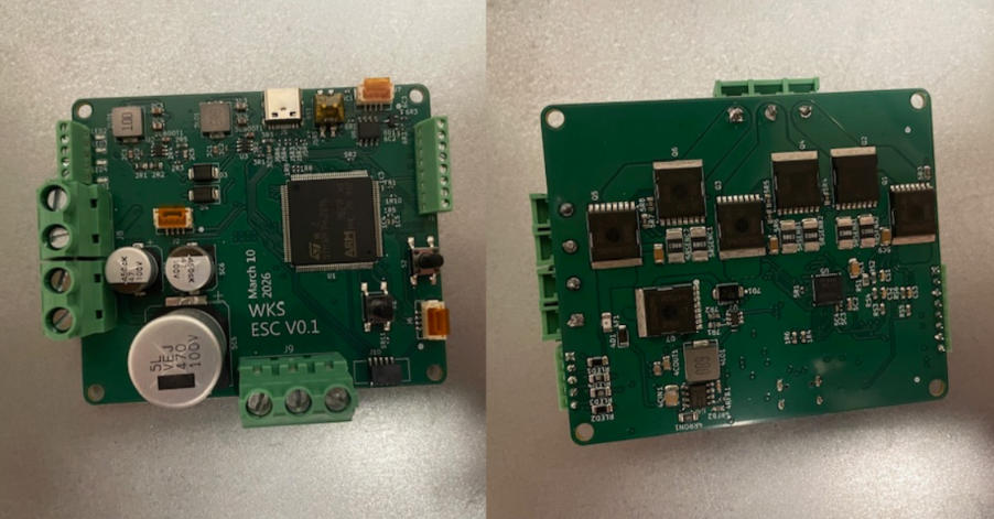
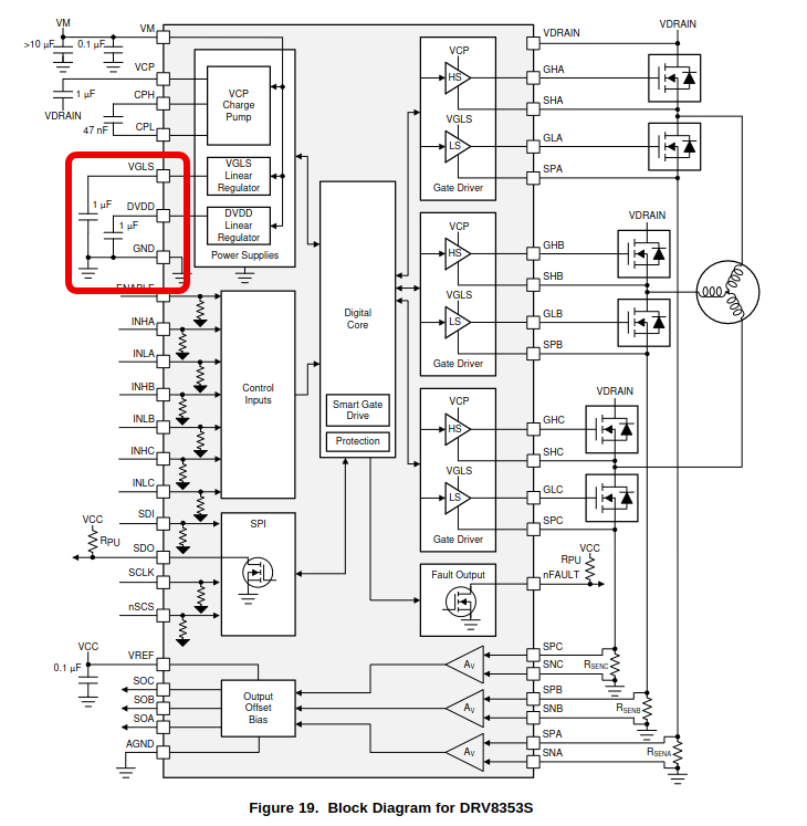
My first version missed key components for the DRV8353S circuit. I was excited to get the board manufactured and didn’t give it a look over – I forgot the 1uF decoupling DVDD capacitor (red arrow) and misplaced the VGLS 1uF decoupling capacitor with a resistor (blue arrow).
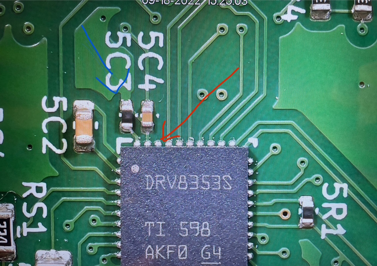 Missing cap on the red arrow pin, and resistor in place of where a cap should be (blue arrow).
DVDD is the 5-V internal regulator output. Without the capacitor, the IC cannot regulate its voltage internally and the board wont function. VGLS is the 11V internal regulator output. Without the capacitor, the IC cannot generate the 11V that is used for turning on and off the transistors.
I was able to tack some capacitors into place to get a demo going but I definitely learned a lot about checking my work with these mistakes.
Overall – I made a lot of mistakes with this project. Each one has made me learn “the hard way” by burning money on components and has made me improve my design skills.
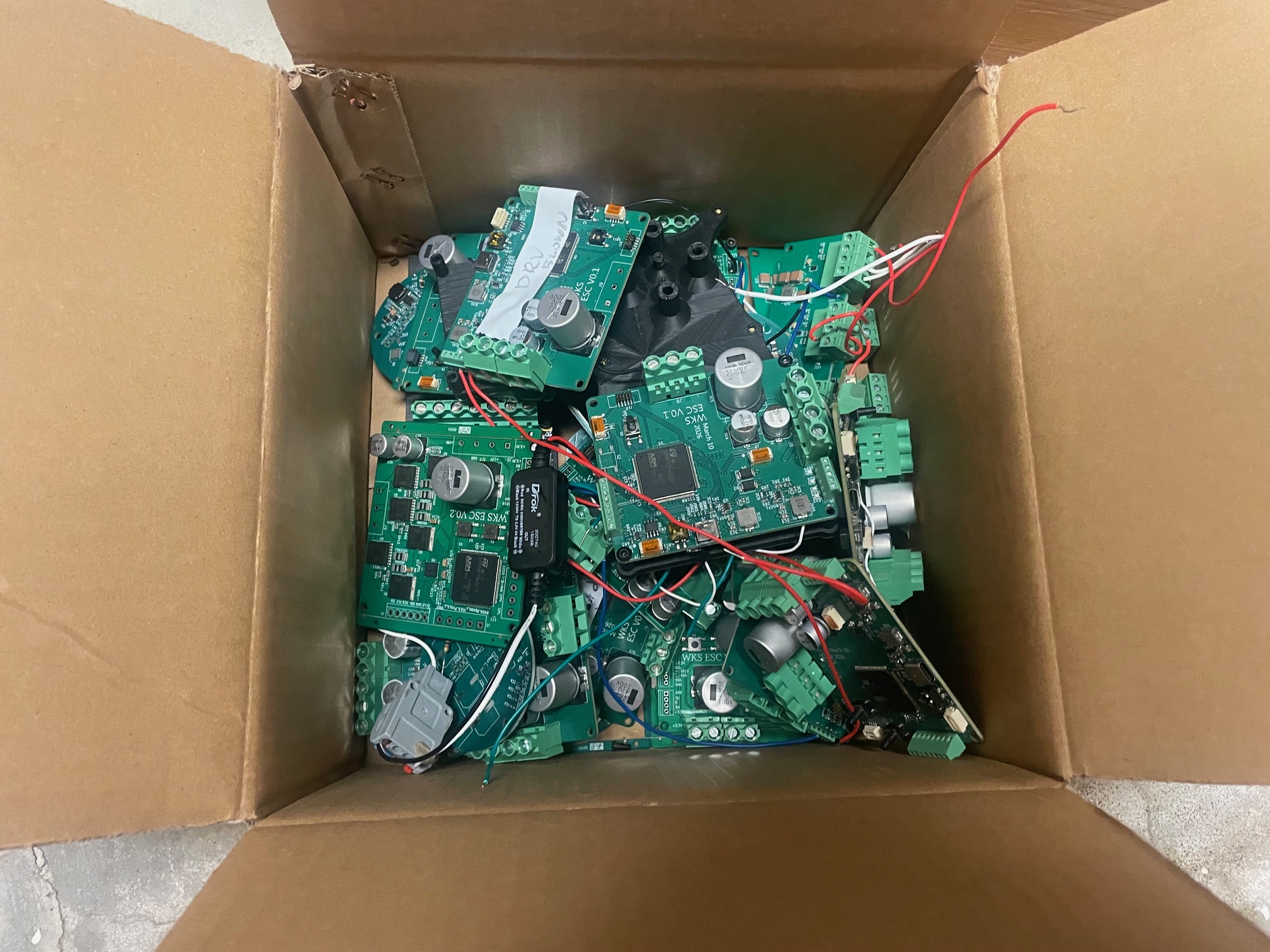
Graveyard
Mechanical Design
I designed the mechanical assembly in Onshape. It uses two cycloidal disks positioned 180 degrees out of phase to reduce vibration, with bearings at each rotating interface to reduce friction.
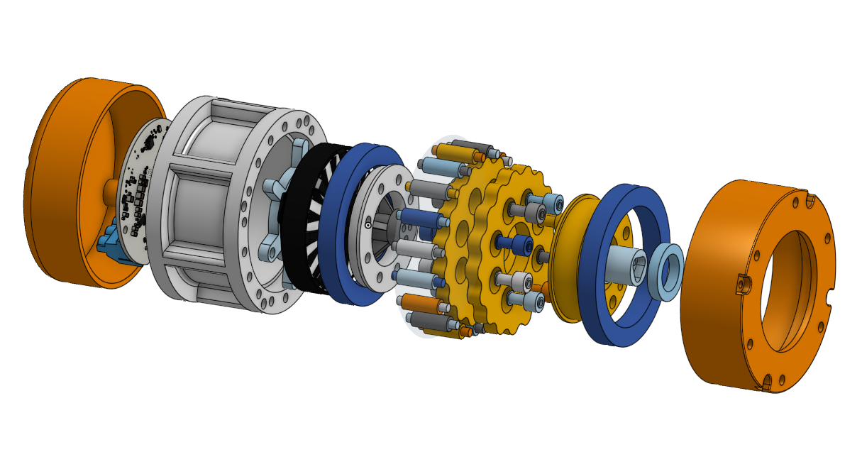 Exploded view
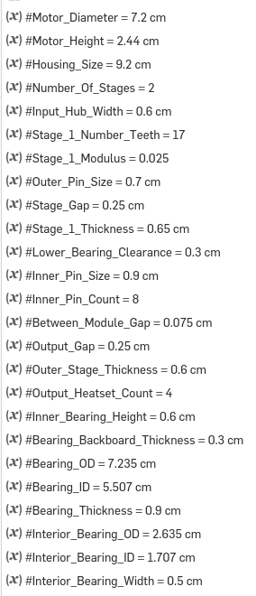
The key dimensions are parameterized so the design can accommodate different motors, gear ratios, and output bolt patterns.
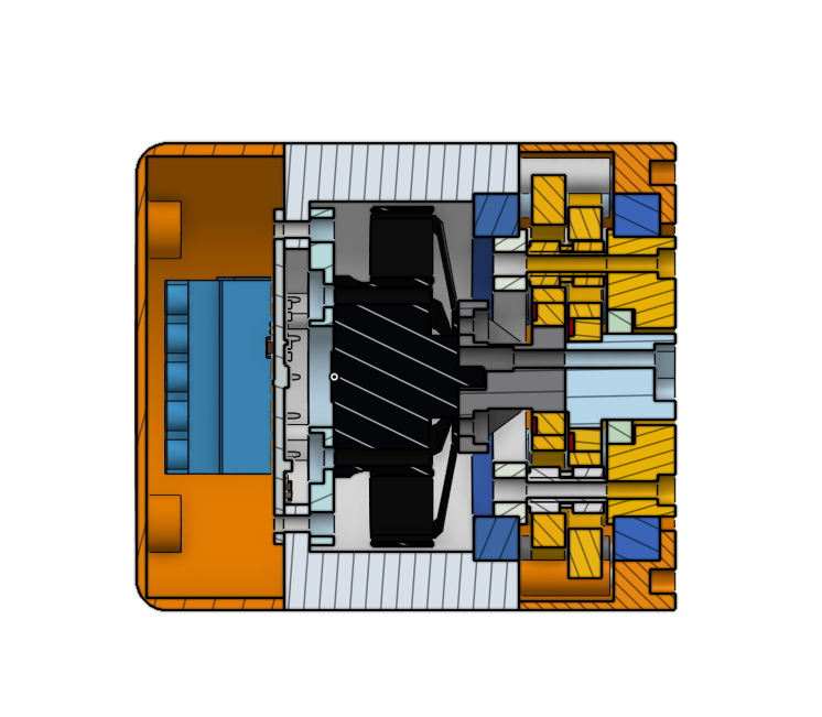 Section view
Tuning the tolerances required the most iteration because they directly affect efficiency and backlash.
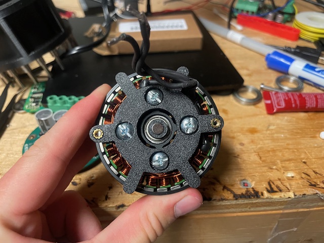 Back motor mount install
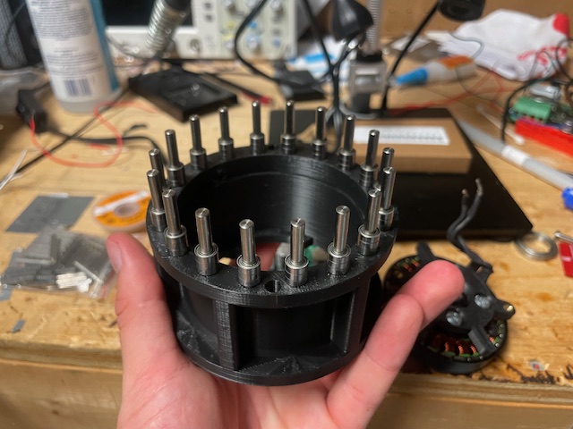 Pin install
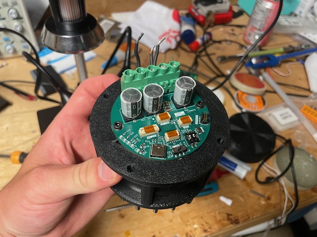 PCB install
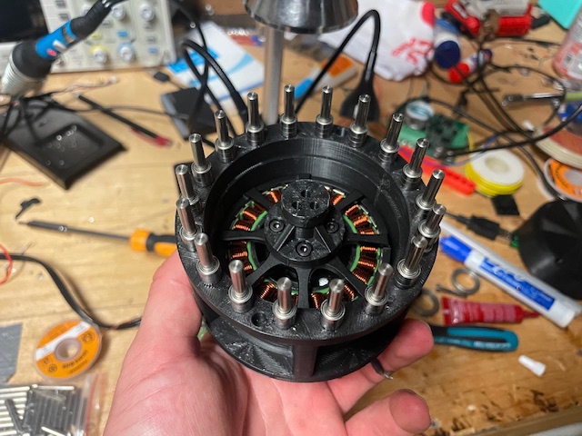 First eccentric shaft
First cycloid install
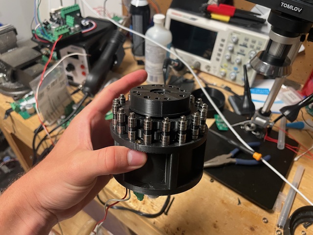 Output shaft install
Controls
6-Step Commutation
Speed Control Test with 19:1 Cycloidal Gearbox Space Vector PWM Implemented 6-Stage Commutation with varying target velocity
Exploded view of the cycloidal gearbox






















Related albums
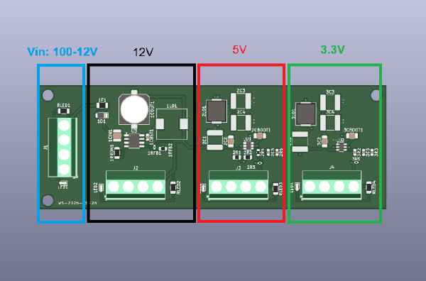
Three-Stage Buck Converter
- Designed a three-stage board providing 12 V, 5 V, and 3.3 V power rails.
- Validated the 10 W supply under load and measured output ripple with an oscilloscope.
- Used the prototype to de-risk power delivery for a larger custom motor controller.
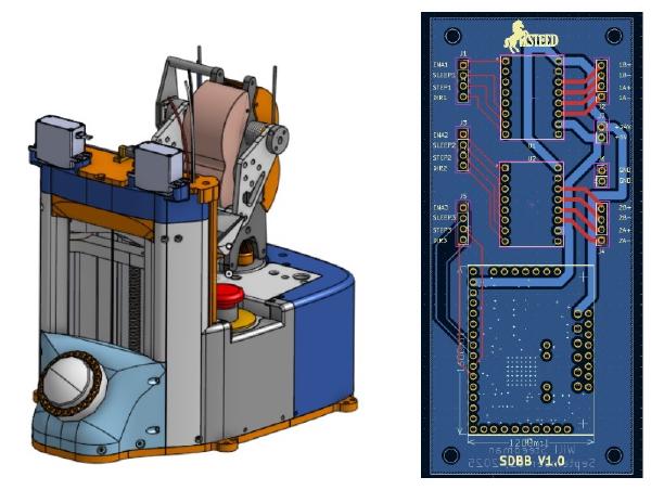
Automated Dog Treat Launcher
- Built an automated treat dispenser with a lead-screw elevator and differential turret.
- Integrated servos, sensors, custom PCB wiring, and jam detection.
- Programmed an autonomous daily dispensing cycle with fault handling.
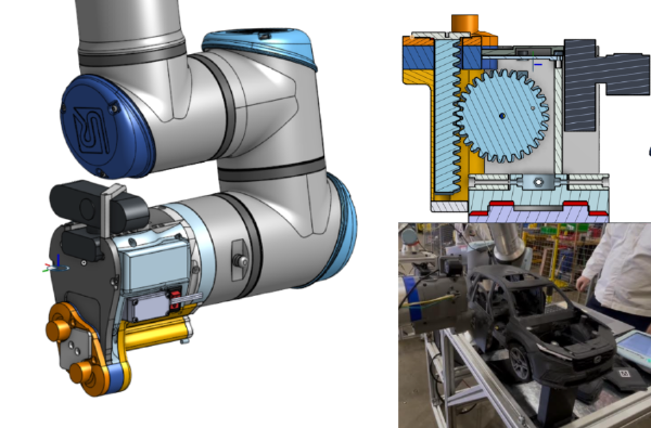
Honda Cobot Assembly Demo
- Helped create a UR10e cobot demo that assembled a 3D-printed Honda CR-V model.
- Designed a magnetic rack-and-pinion end effector with Arduino-controlled tooling.
- Achieved a 100% assembly success rate throughout the public demo day.