Designing a 3D Printed Robot Arm to Clean My Room
Project at a glance
- Built a four-degree-of-freedom, 3D-printed robot arm with a half-meter workspace.
- Integrated the mechanics, stepper electronics, limit switches, and custom wiring.
- Implemented homing and basic kinematics for a 2 kg payload prototype.
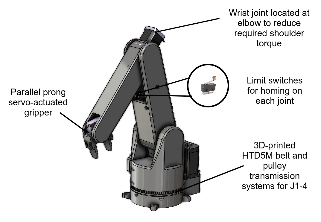 Final CAD for Goose V1
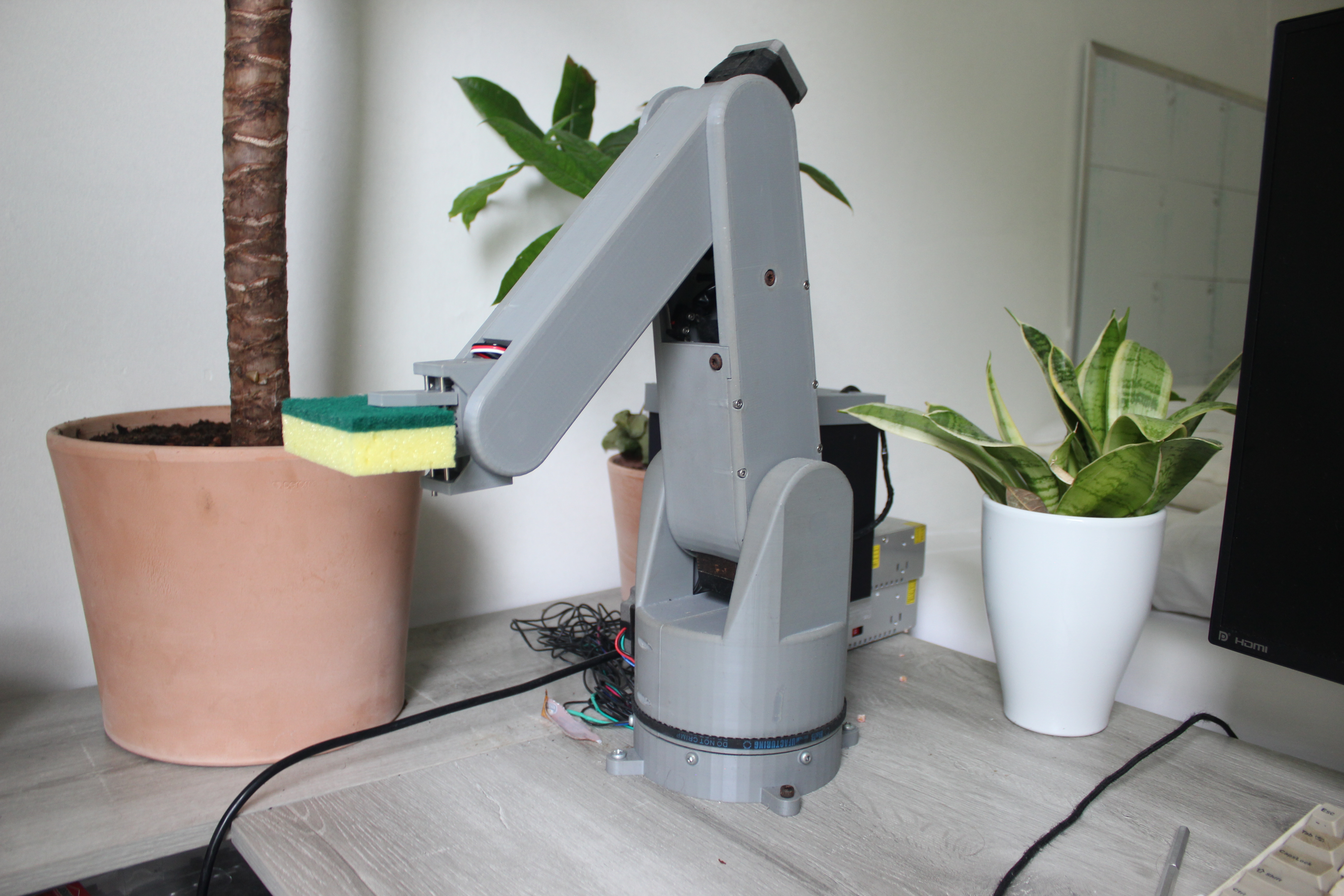
I always have a messy desk. To fix it, I designed, assembled, and programmed an open-source, four-degree-of-freedom, half-meter-workspace, 2 kg-payload, 3D-printed robot arm that can pick up objects and wipe countertops.
Experience, Learning & Skills
Experience & Skills
-
I followed Shigley’s Engineering Design Process through many iterations of mechanical, electrical and software design.
-
I developed skills in full-system mechanical design in SolidWorks, modular and parametric part design, electronic circuit design and debugging, microcontroller hardware integration, and elementary robotic control (FKin and IKin).
Learning
-
Be dumb enough to start but smart enough to learn - I didn’t think too hard about starting a larger project like this one or else I would have scared myself off from actually doing it. I found that it is best to embrace the unknown and adapt quickly to design problems as they present themselves.
-
Design parts to fail (in CAD and physically) - I iterated on the wrist design approximately 20 times. Initially, I created a new SolidWorks part and redesigned the geometry from scratch for every revision, which was extremely inefficient. A better approach is to fix the high-level geometry early and parameterize sketches around it. This keeps iteration within one part and limits changes to controlled dimensions. I also learned to modularize parts for quick replacement. When a large, hard-to-reach component fails, remanufacturing and reassembling it can create a major setback. Discrete, exchangeable, and spatially thoughtful parts save time during iteration.
Motivation
I think robot arms are beautiful paradoxes; complicated in most engineering aspects, but perform tasks like picking up objects that are ostensibly so simple. This project was motivated to explore and learn from these engineering complexities and attempt to execute some simple tasks like picking up objects and following trajectories.
This video demonstrates the mechanical complexity of spherical wrists. Designers must transmit rotation from actuators near the elbow to mutually perpendicular wrist joints.
Technical Details
Mechanical
The mechanical design took approximately six months and 15 iterations to refine. Belt drives allowed me to reposition heavy motors to better balance the linkage loads.
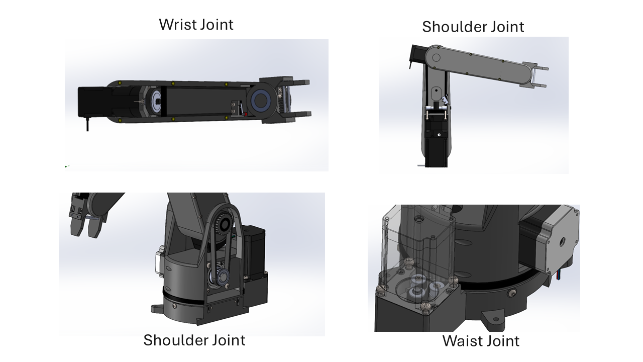
Because I selected lower-cost open-loop stepper motors, I needed another way to establish each linkage position relative to its end stop. I used limit switches for homing.
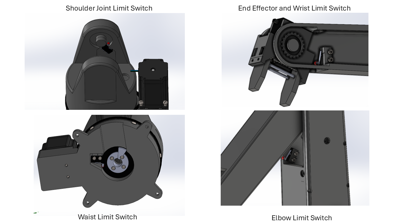
I selected a linear-rail, rack-and-pinion gripper inspired by Chris Annin’s design. The servo provides basic tactile feedback by detecting the onset of a stall, although a dedicated force sensor on the finger would be more responsive.
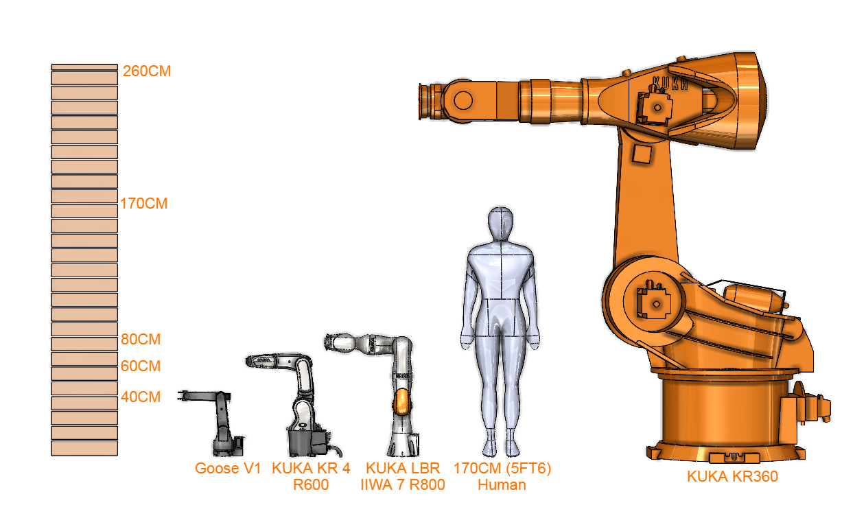
For scale, here is Goose V1 beside several industrial KUKA robots and a person.
Electrical
The mechanical sensor and actuator choices determined the electronics architecture. Two 36 V, 480 W power supplies connected in parallel power four stepper motors—three NEMA 23 motors and one NEMA 17—and their drivers. The combined rating is comparable to some microwaves or small ovens.
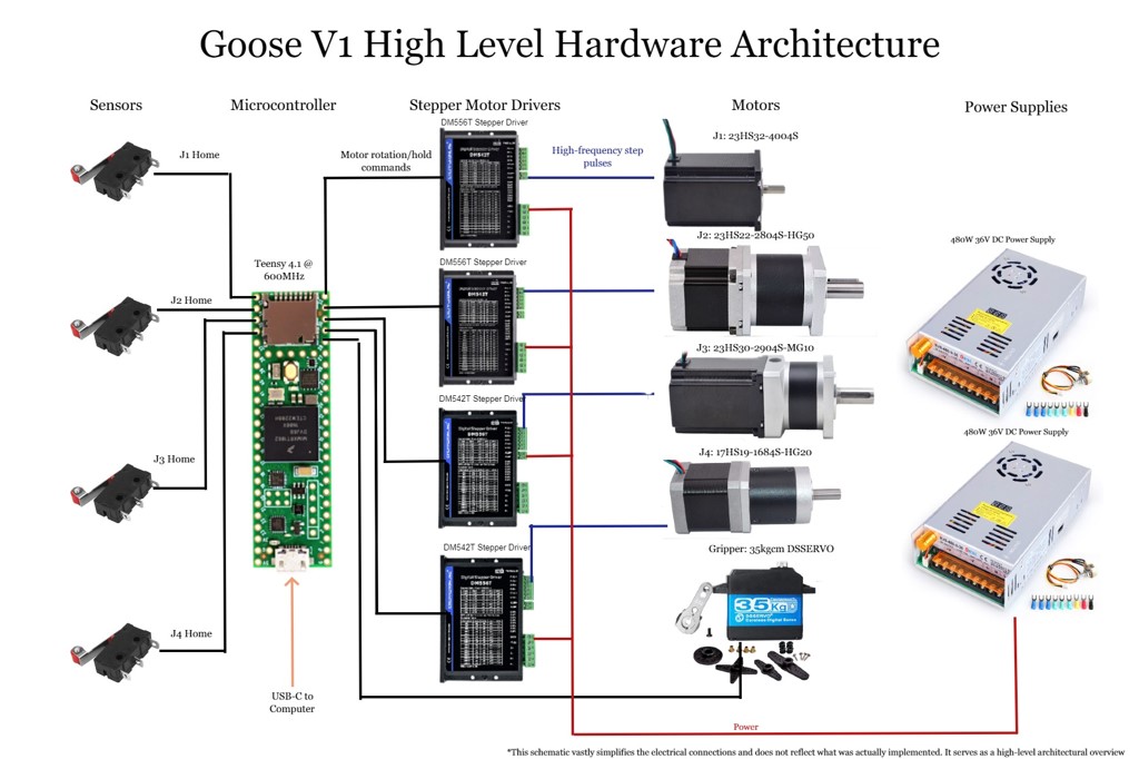
Stepper-motor drivers translate pulse signals from the Teensy 4.1 into the controlled phase currents required by the motors. They also protect the control electronics and strongly influence motion quality and reliability.
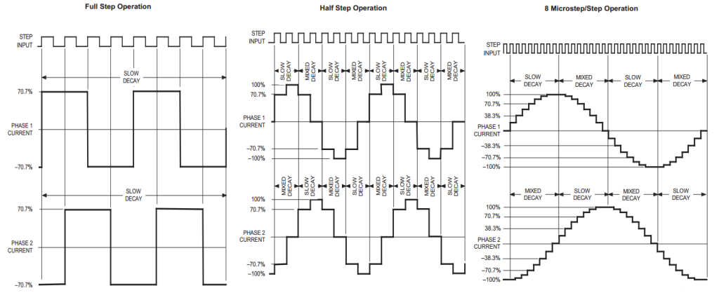 The microcontroller supplies square-wave step pulses (top), while the driver regulates the motor phases as stepped sinusoids. Increasing the microstep resolution produces smoother motion at the cost of incremental torque.
After several A4988 drivers failed, I replaced them with more robust StepperOnline DM556T and DM542T drivers that met the voltage and current requirements. I enclosed the electronics for compactness and protection, although the cable management still has room for improvement.
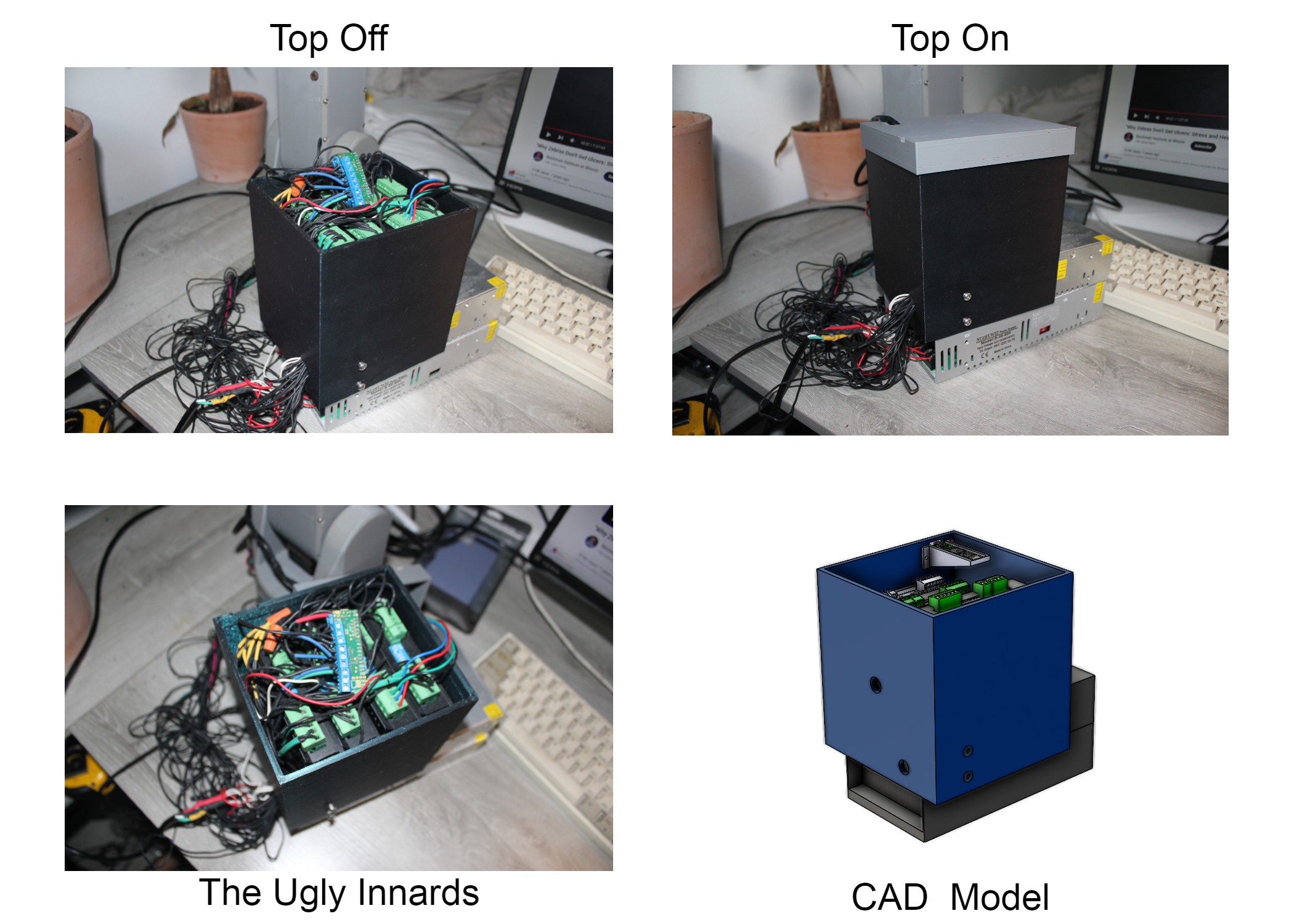
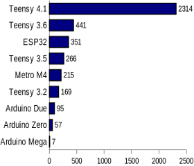
The final electronics upgrade was replacing an older Arduino ATmega board with a Teensy 4.1. Its 600 MHz clock and 1,024 KB of SRAM provided much more computing headroom for smoother kinematics.
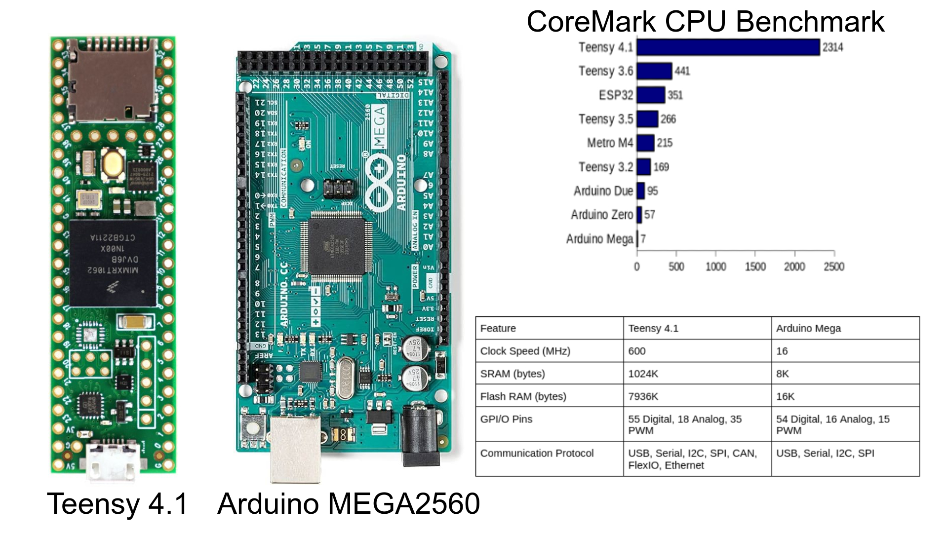
The Teensy 4.1 performs 330.57 times better than a standard Arduino Mega when tested on a CoreMark CPU Benchmark
Software
I started by developing a homing algorithm that moves each linkage toward its limit switch until contact establishes a known reference position.
I simplified the mathematical model to reduce computation. First, I controlled only the end-effector position, not its orientation. Second, I approximated the three-link robot as an open-chain, two-link mechanism, leaving two variables to solve instead of three.
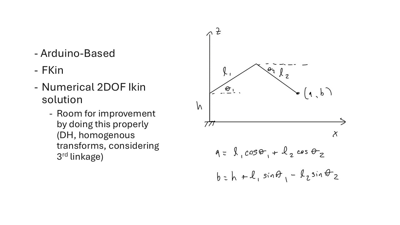
Using this model, FKin became trivial because it was simply a matter of plugging in Theta1 and Theta2 into the two nonlinear equations in the diagram.
For inverse kinematics, I expressed Theta1 in terms of Theta2 and searched the possible values for the solution with the lowest error.
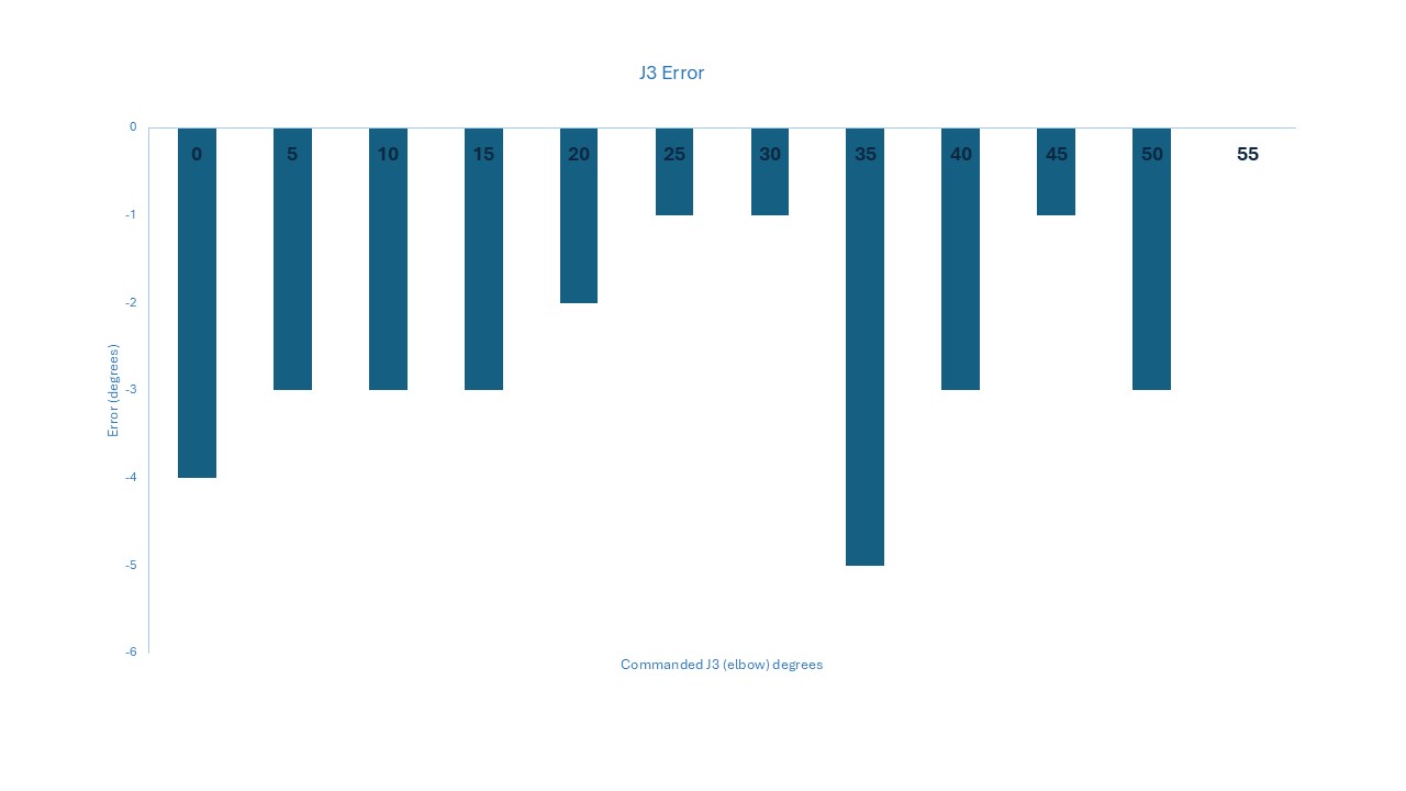
The model is computationally inefficient and geometrically approximate, but it was sufficient for this prototype. The remaining linkage-angle errors likely came from imperfect belt geometry, belt slip, and stepper-position loss under load. A future revision would use a more rigorous manipulator model and closed-loop joint feedback.
I learned a lot from this project! I have been reading Robot Modelling and Control by Spong and hope to apply the ideas in a future project.