10 W Three-Stage Buck Converter
General-purpose three-stage DC-DC converter
Project at a glance
- Designed a three-stage board providing 12 V, 5 V, and 3.3 V power rails.
- Validated the 10 W supply under load and measured output ripple with an oscilloscope.
- Used the prototype to de-risk power delivery for a larger custom motor controller.
Why?
For my ESC project, I needed to support several component voltages. The STM32 MCU is only 3.3 V tolerant on most pins, the external MOSFET cooling fan operates at 5 V, and the power MOSFETs require a gate-source voltage of 12 V. I needed an efficient way to convert an input of up to 100 V into these rails. I designed a test board using the LM5164 and TPS54302 before spending hundreds of dollars to manufacture the full ESC. The prototype also gave me an opportunity to improve the layout before integrating it into the larger board.
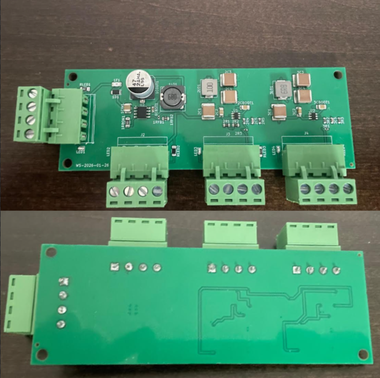
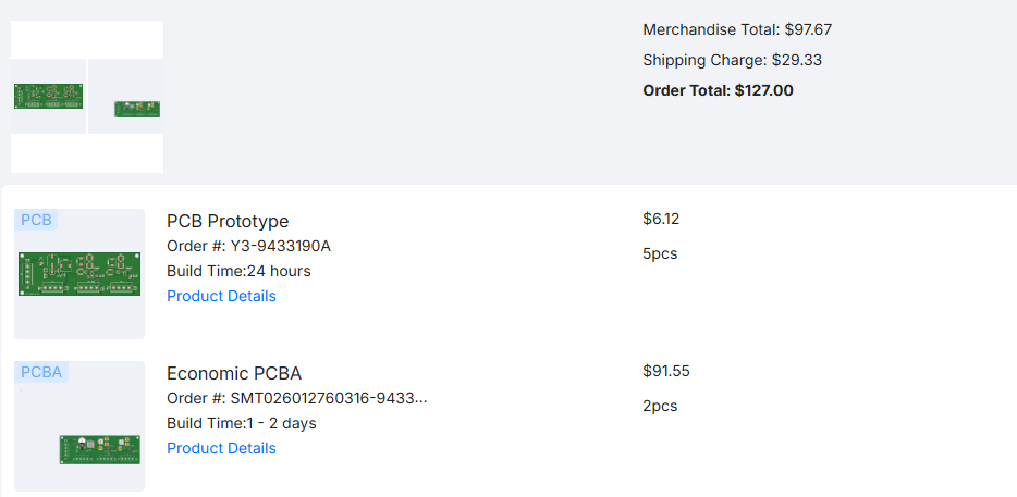
Finished assembly by JLCPCB
What?
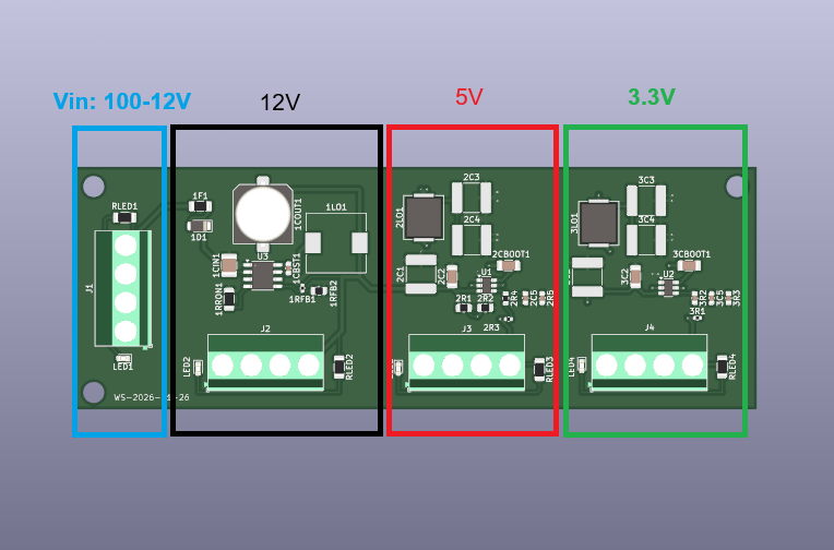
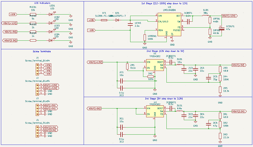
The board has three stages, each centered on a buck-converter IC, with LEDs for power indication and screw terminals for each output. The total output power is conservatively 10 W: approximately 1 A on the 12 V stage, 2 A on the 5 V stage, and 3 A on the 3.3 V stage.
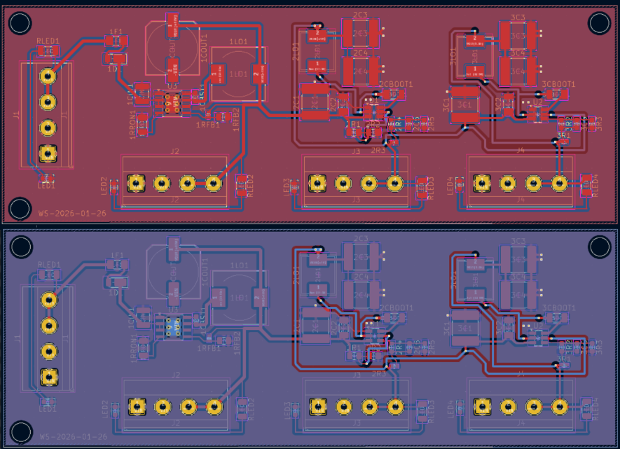
All of the components and most of the routing live on the top side of the board – that way JLC didn’t have to flip the board to solder components on both sides, saving me money. The board is two layers – more wasn’t necessary.
I tested the 12 V output with a hobby DC motor rated for 11 W, slightly above what the converter can provide. The LEDs for stages two (5 V) and three (3.3 V) turn off because the motor consumes the available current, leaving too little for the secondary and tertiary converters to regulate.
The same thing happens when the load is applied at 5 V: the 3.3 V stage turns off.
Overall, this board is suitable for low-current components with specific voltage requirements, such as MCUs, sensors, and LEDs.
How?
A buck converter uses internal MOSFETs to switch the input voltage on and off at high frequency. The average output falls somewhere between the input voltage and ground based on the duty cycle, which these chips set using two feedback resistors. A series inductor resists sudden current changes, while a parallel capacitor filters the switching ripple to produce a steadier output.
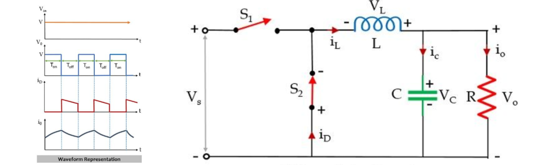
This is a good article if interested.
I designed the board in KiCad using the LM5164 and TPS54302 datasheet layout recommendations. Both designs follow the same principle: keep the bootstrap capacitor and feedback resistors close to the IC to reduce noise and parasitic effects.
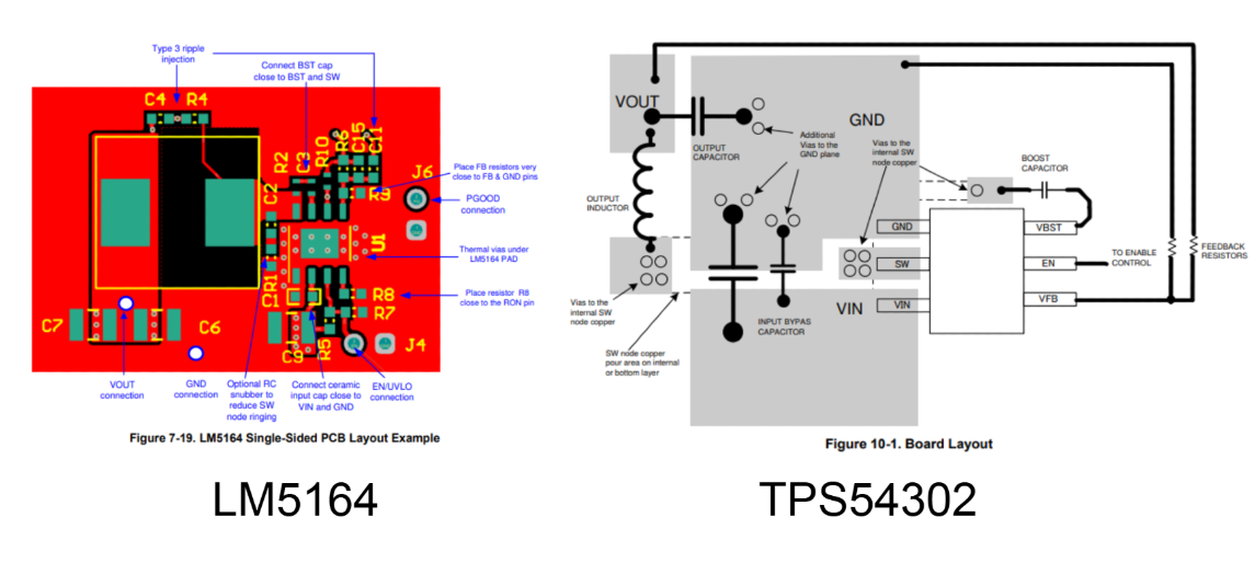 Layout References
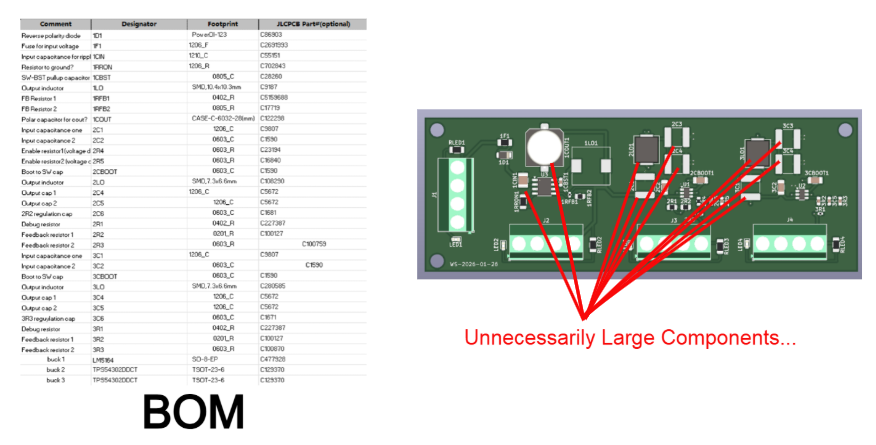
I used JLCPCB’s online parts database to select the remaining components. Because this was one of my first surface-mount PCBs, I conservatively oversized many parts. That decision explains some of the comically large capacitors and inductors. For the ESC implementation, I replaced many 1206 and 0805 packages with 0402 and 0603 parts to save space.
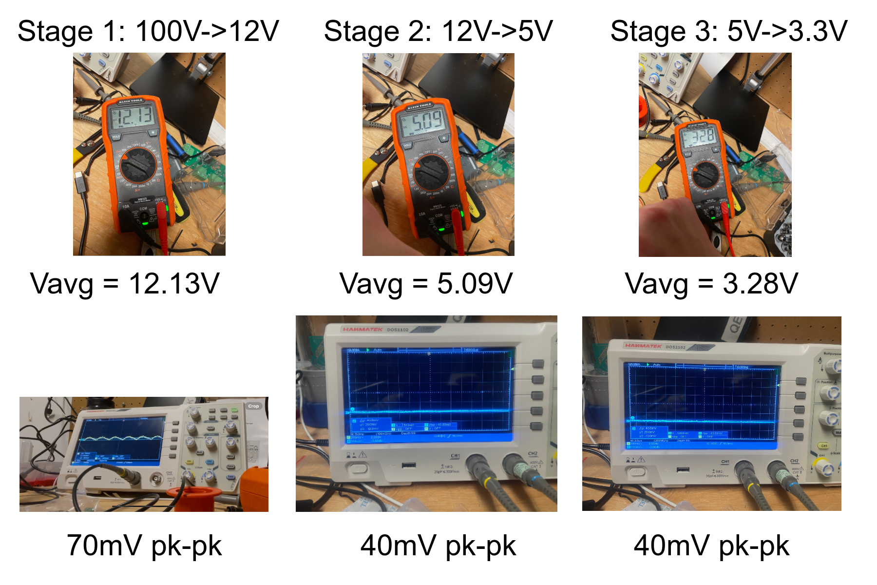
I used an oscilloscope to measure the output ripple for each stage. The LM5164 (12 V) stage had more ripple than expected at approximately 70 mV peak-to-peak. The other two stages measured approximately 40 mV peak-to-peak.
Takeaways
The project produced two main takeaways:
- Trace length and component placement are critical. Long connections increase parasitic effects and noise. In this design, placing the inductor and output capacitors close to the converter minimizes loop area and output ripple.
This video gave some good insight
- PCB assembly can dominate the prototype cost. Fabricating the board cost less than $15, while third-party assembly cost approximately $200. Selecting JLCPCB “Basic” parts where practical can reduce that expense.
 USD
USD









Related albums
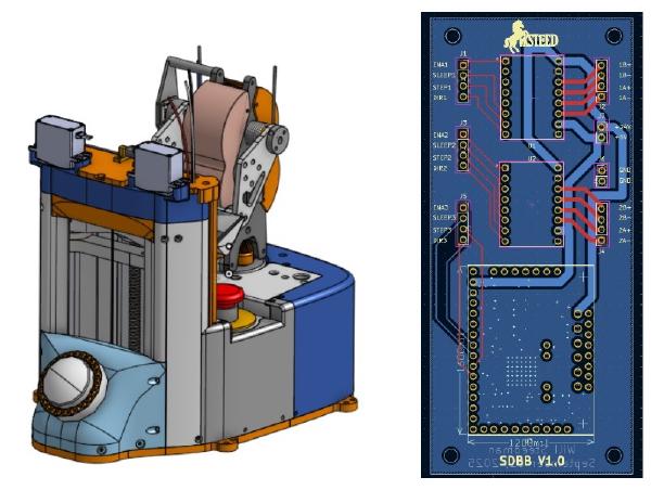
Automated Dog Treat Launcher
- Built an automated treat dispenser with a lead-screw elevator and differential turret.
- Integrated servos, sensors, custom PCB wiring, and jam detection.
- Programmed an autonomous daily dispensing cycle with fault handling.
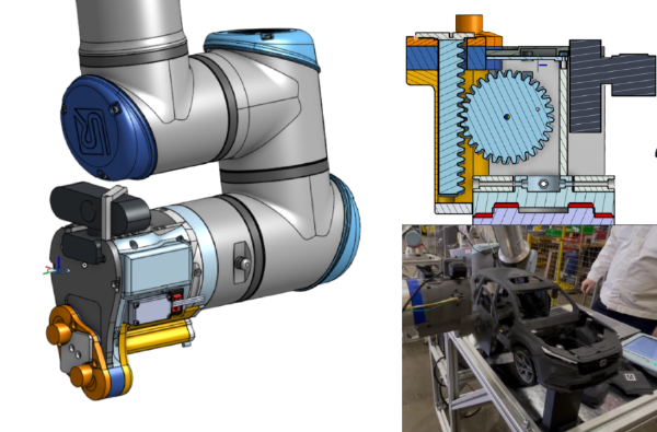
Honda Cobot Assembly Demo
- Helped create a UR10e cobot demo that assembled a 3D-printed Honda CR-V model.
- Designed a magnetic rack-and-pinion end effector with Arduino-controlled tooling.
- Achieved a 100% assembly success rate throughout the public demo day.
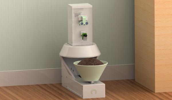
Autonomous Pet Feeder
- Built an Arduino-controlled feeder with a stepper-driven auger and servo-driven bowl carriage.
- Integrated ultrasonic, infrared, camera, and limit-switch sensing with a responsive state machine and web UI.
- Calibrated repeatable three-second servings and offloaded camera-based pet identification to a Flask server.